TaxiBot
Objective: Design and fabricate a robot that starts in a 30 x 30 x 30 cm cube atop a 130 cm post, descends to pick up a plastic action figure, ascends, deposits the action figure onto a shelf at the top of the post, and returns to the 30 x 30 x 30 cm cube; this must be completed using as little electrical energy as possible.
Skills Learned:
Pulley systems.
Rack and pinion drive system.
3D CAD SolidWorks.
Laser Cutting
Role:
Design/ manufacture the chassis stabilizing mechanism.
Design the passenger retrieval mechanism.
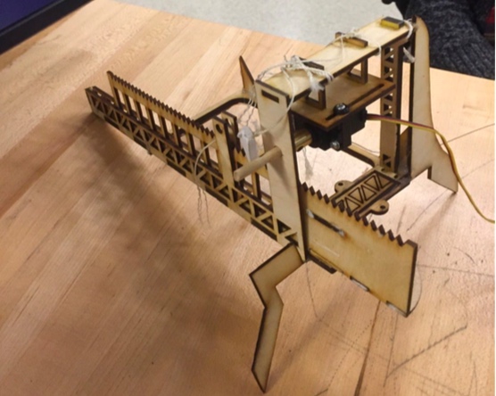
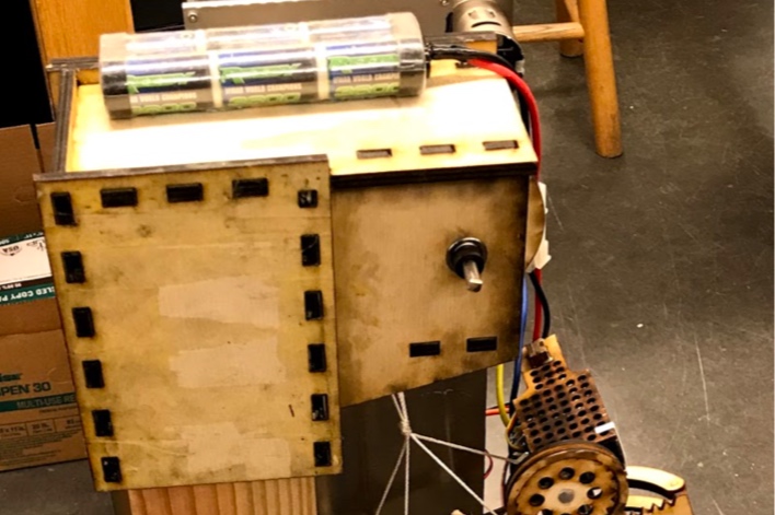
Final Bot
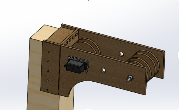
SolidWorks of Final Bot

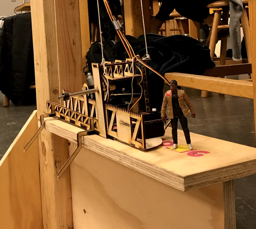
TaxiBot in Action
Key Components
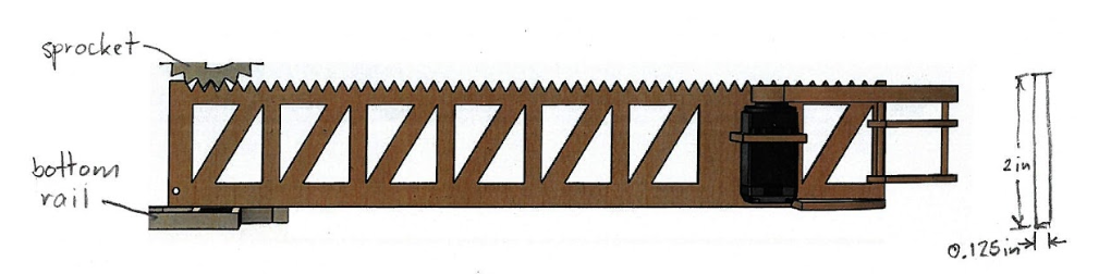
Passenger Retrieval Mechanism
The final design for the passenger retrieval mechanism was a plywood rack and pinion with a single servo-controlled barrier. A servo-driven 16-teeth plywood sprocket mounted on the the lower chassis was used to drive the the plywood rack towards the passenger so that they are within reach of the servo-controlled barrier which then gently swept the passenger onto a platform. Entrapped between the jaw, rack, servo, and platform, the passenger could then be transported from the lower platform to the upper platform.


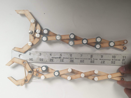
Alternative Passenger Retrieval Mechanism Designs
Several variations of the passenger retrieval mechanism were explored over the course of the term. Designs considered consisted of a bucket drop idea, a platform with two claws controlled by servos, as well as a scissor joint design. Each one of these mechanism were tested and many disadvantages became apparent.
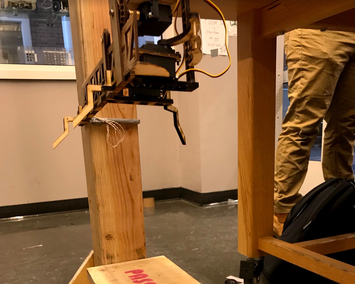

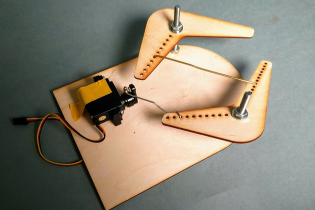
Chassis Stabilization Mechanism
The final design for the post stabilizing mechanism was a servo powered device that locks the lower chassis onto the lower platform. The design contained three fins, one on the right and two on the left. The two fins on the left were kept fixed, while the fin on the right was designed to be capable of rotating 90 degrees. The fins original position was at a 45 degree angle so when the bot has landed on the lower platform the fin will lock itself onto the platform and straighten itself.


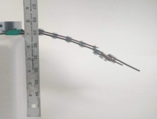
Alternative Chassis Stabilization Mechanism
Several variations of the chassis stabilization mechanism were explored over the course of the term. Designs considered consisted of a triangle stabilization, a post holder, and a fixed lock design. Each one of these mechanism were tested and many disadvantages became apparent.
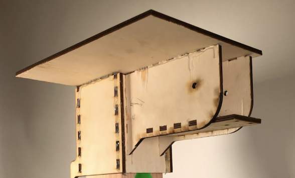
Post Gripping Mechanism
The final design for the post gripping mechanism was altered from the original robust structure because of the multiple design changes that occured in the final week. The original post gripper was designed to withstand the large weight incorporated in the counter weight. The counter weight brought its own complexities and time constraints that did not allow the idea to be further pursued. As a result of this design change, the upper chassis post gripper simplified and was easier to assemble. The new post gripper featured a post attachment point that was ½ the size of the original, utilizing a clamping system to eliminate the need for the chassis to fully wrap around the post that was adapted from another group’s design. When compared to previous design iterations, the final design has the longest pulley arm. This was introduced to allow the addition of three pulleys rather than a three channel pulley. This design element more space between the triangle guide system that is responsible for preventing lower chassis rotation.

Alternative Post Gripping Mechanism
Several variations of the post gripping mechanism were explored over the course of the term. Designs considered consisted of full wrap around designs that hugged the post like a cap. Each one of these mechanism were tested and many disadvantages became apparent.