Omni-Directional Vehicle
Objective:
Design and manufacture an omni-directional vehicle. Omni-directionality is defined by the ability to move in all directions while facing any direction with a zero turn radius.
Final Vehicle:
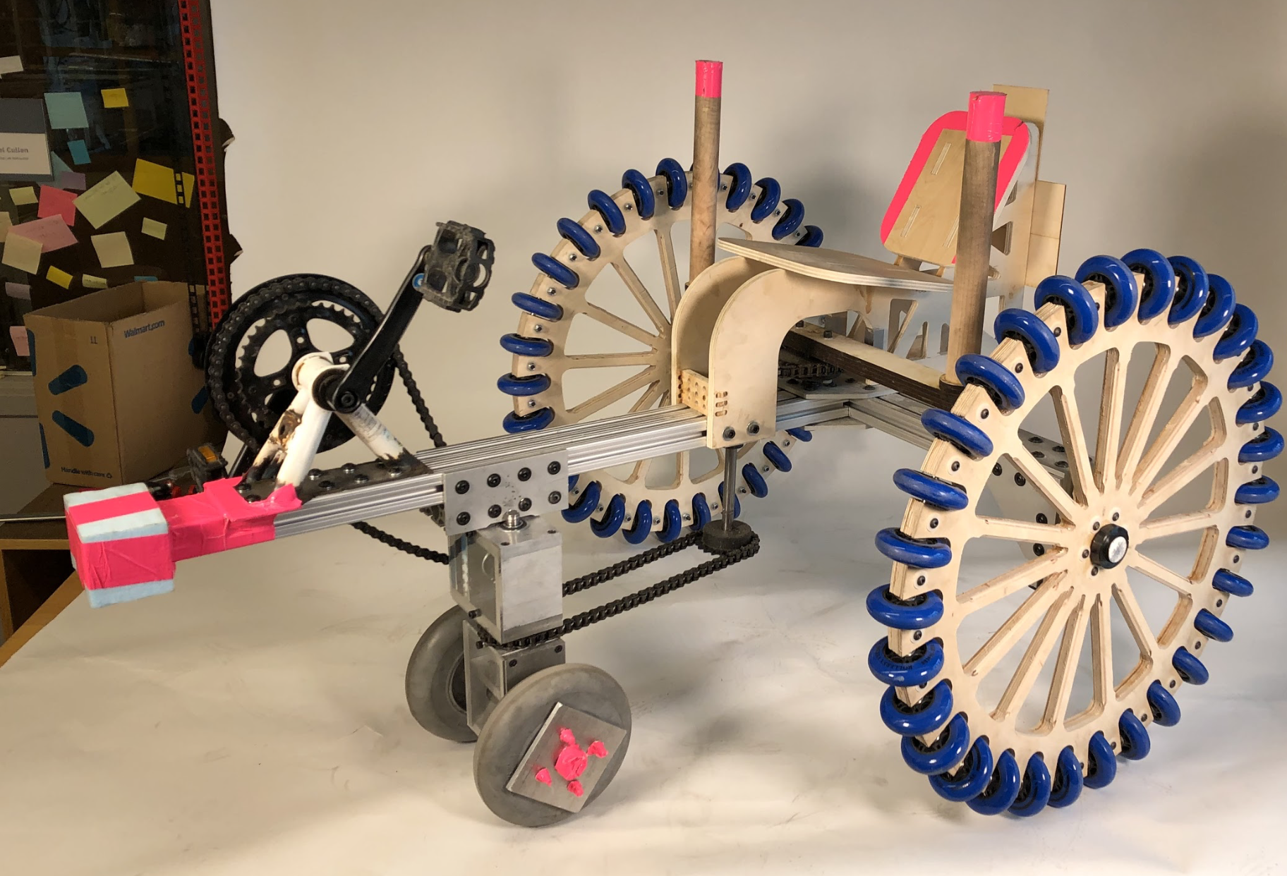
The vehicle consisted of a steered driven wheel and modified wheel chair wheels. The steered driven wheel and the modified wheelchair wheels are powered by foot and arms respectively. The hand powered wheels were then modified to be omniwheels, i.e. to have smaller perpendicular passive wheels along the outside to allow for lateral motion. A combination of using the steered driven wheel and hand powered omniwheels achieved true omni-directionality.
Skills Learned :
-SolidWorks 3D Modeling
-Prototyping
-Machine Shop Skills (Milling, Lathing, Laser Cutting)
-Research/Design
Role :
Mechanical Engineer
Designed/manufactured the 3:1 ratio controls with gear box.
Includes the chassis, wooden handle and gear box.
Competition:
The goal was to design a relatively inexpensive, lightweight (under 100lbs), human powered omni-directional vehicle capable of succeeding in three trials. The trials consisted of a drag race, drift race, and maze course. Each event tested the vehicle in key components such as linear speed, angular speed, translational motion, and zero radius turning.


Race Day:
The vehicle had a bit of a learning curve to pilot, as the steering was affected both by the steering on the powered wheel, as well as direct hand steering of the large omniwheels. However, after a bit of practice we were able to successfully control the vehicle. It was ultimately successful in all of the trials, achieving second place overall out of five vehicles. The Omni-Challenge was completed in 130.03 seconds with 1 penalty, the drag race in 36.62 with 1 penalty, and the Gymkhana in 115 seconds with no penalties. Resulting in a total placement time of 281.65 seconds. The final weight of the vehicle was 97lbs.
Brainstorming Phase:

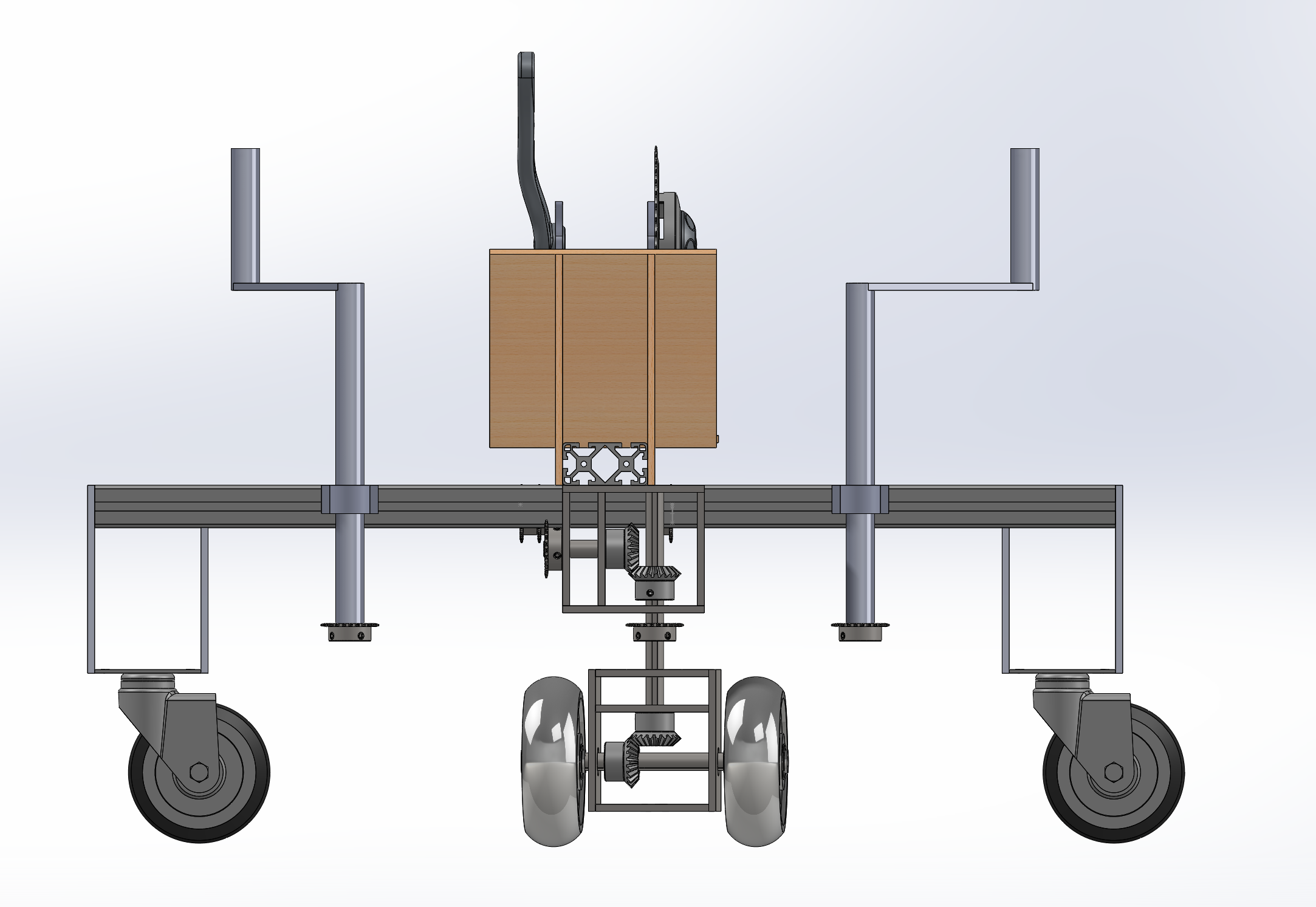


Vehicle idea 1
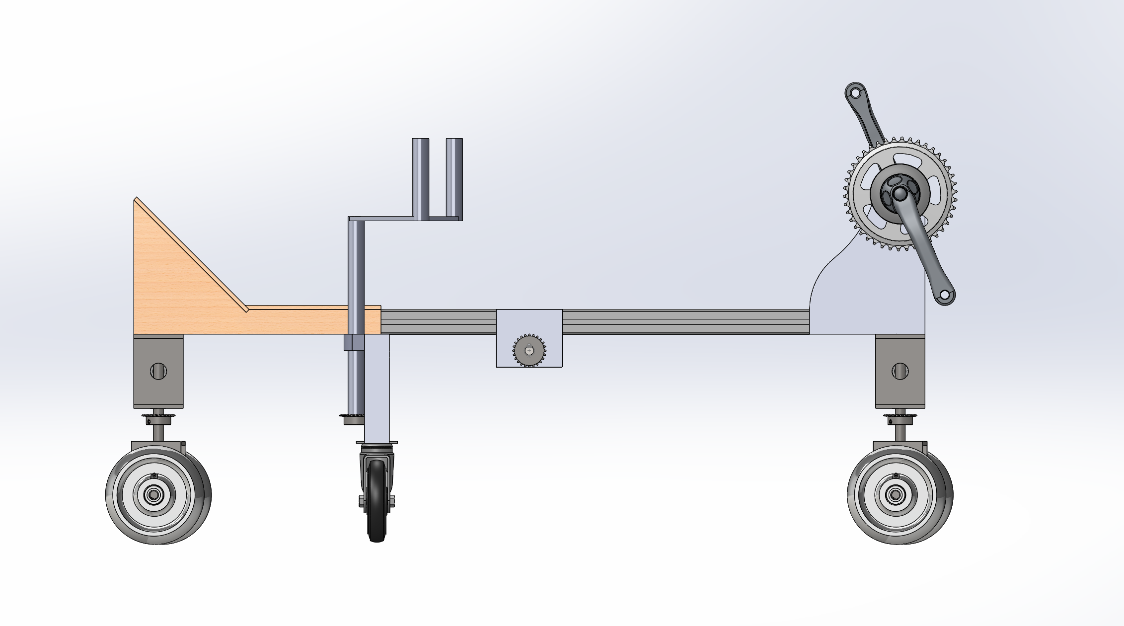
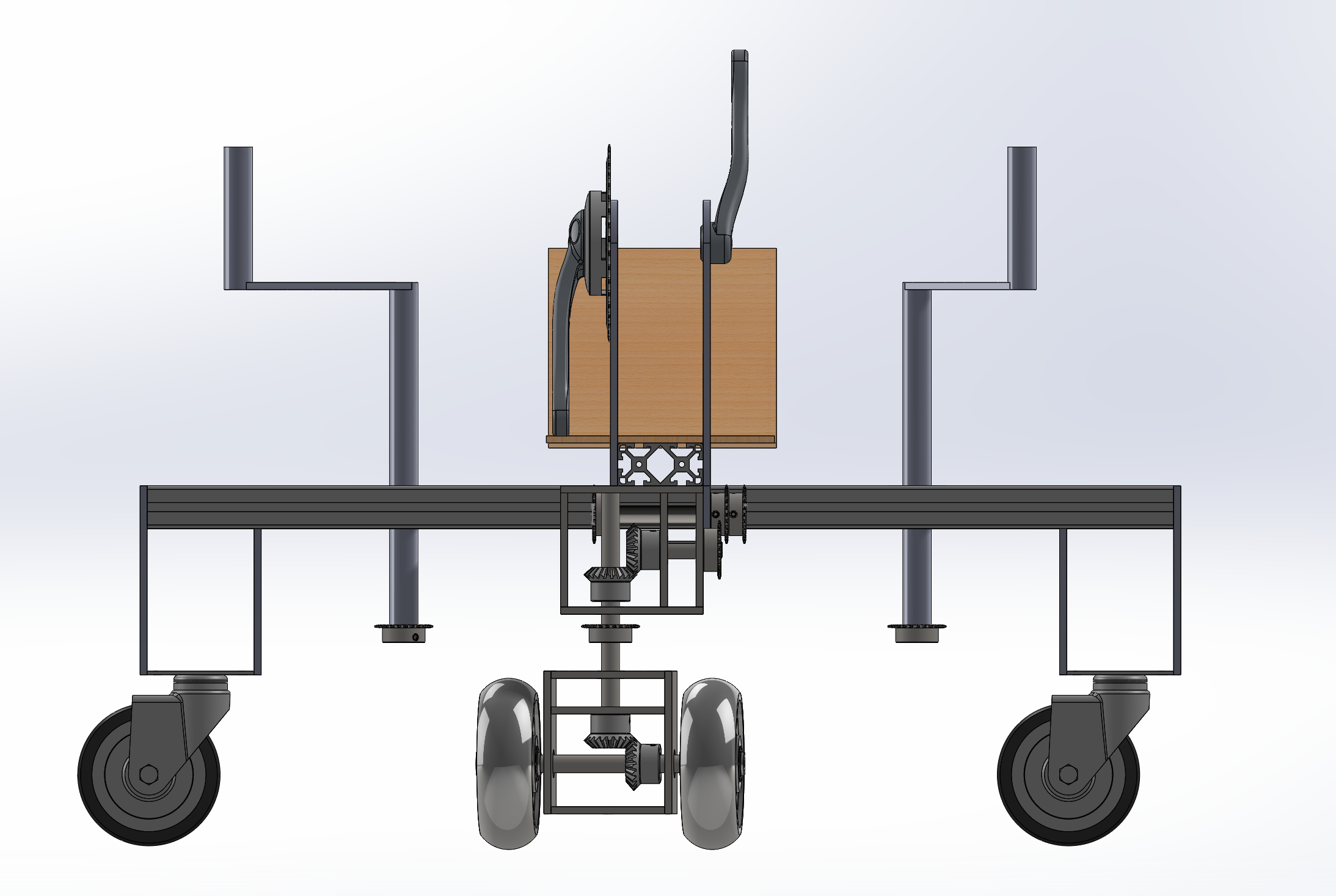
The idea behind this vehicle is that it would have two equally powered wheels in both the front and back of the vehicle. Providing the extra powered wheel in the back will allow for a smoother horizontal translation, because the horizontal forces would be on opposite sides of the center of mass of the vehicle. Both drive wheels would be controlled by the two handles located near the seat. Caster wheels were placed purely for support and prevent vehicle from tipping over. Although this vehicle would dominate in every competition, such as zero radius turning and translation in any direction, this vehicle was ruled out because of weight constraints. The vehicle must remain under 100lbs; SolidWorks analysis showed the vehicle surpass the 100lb limit without including all the minor parts required to build the vehicle. Vehicle was also voted off due to lack of creativity; most successful vehicle from previous year had a similar design.


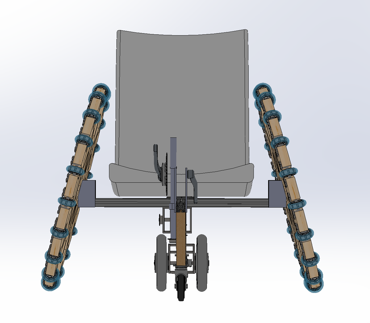
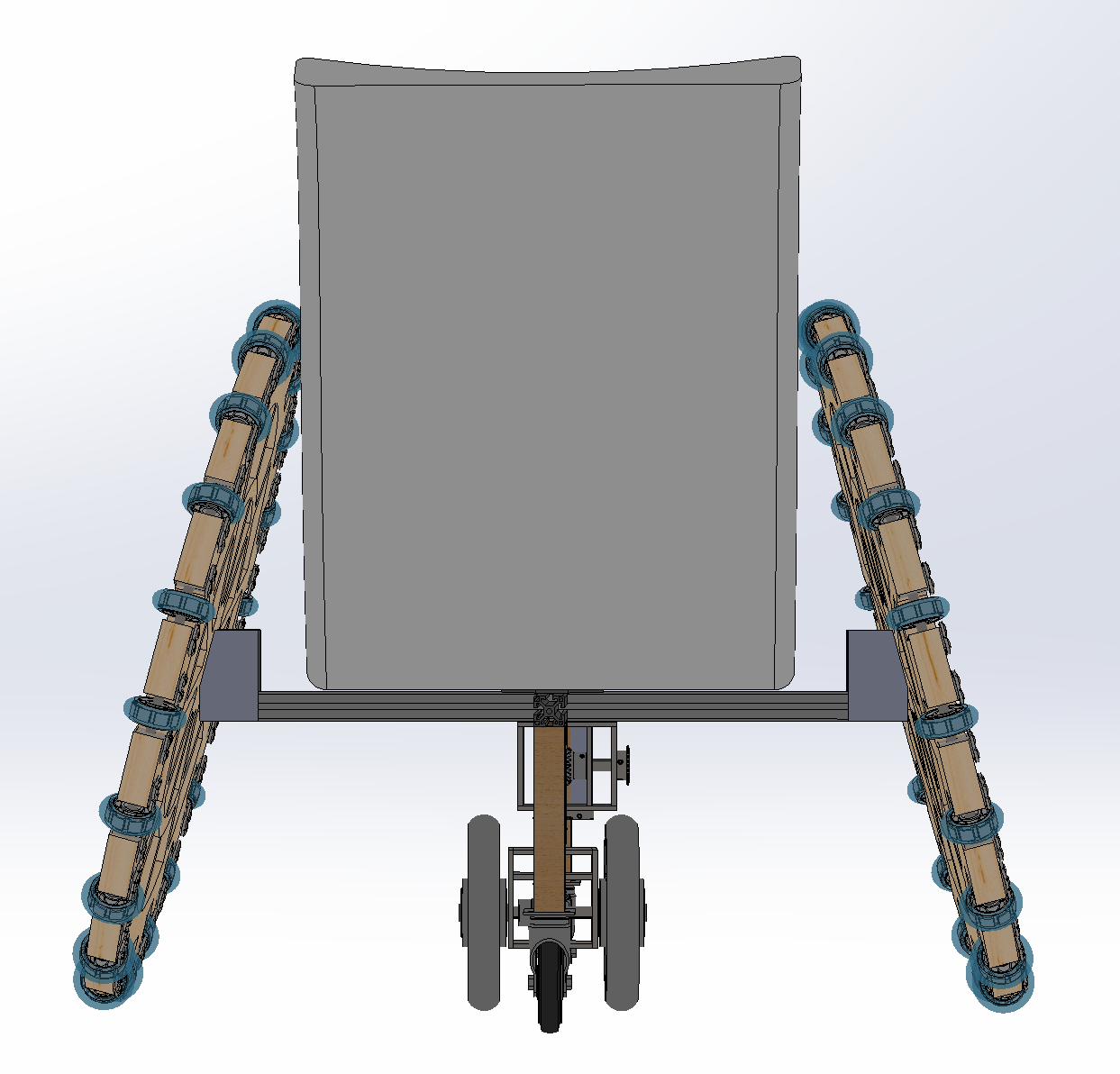

Vehicle Idea 2
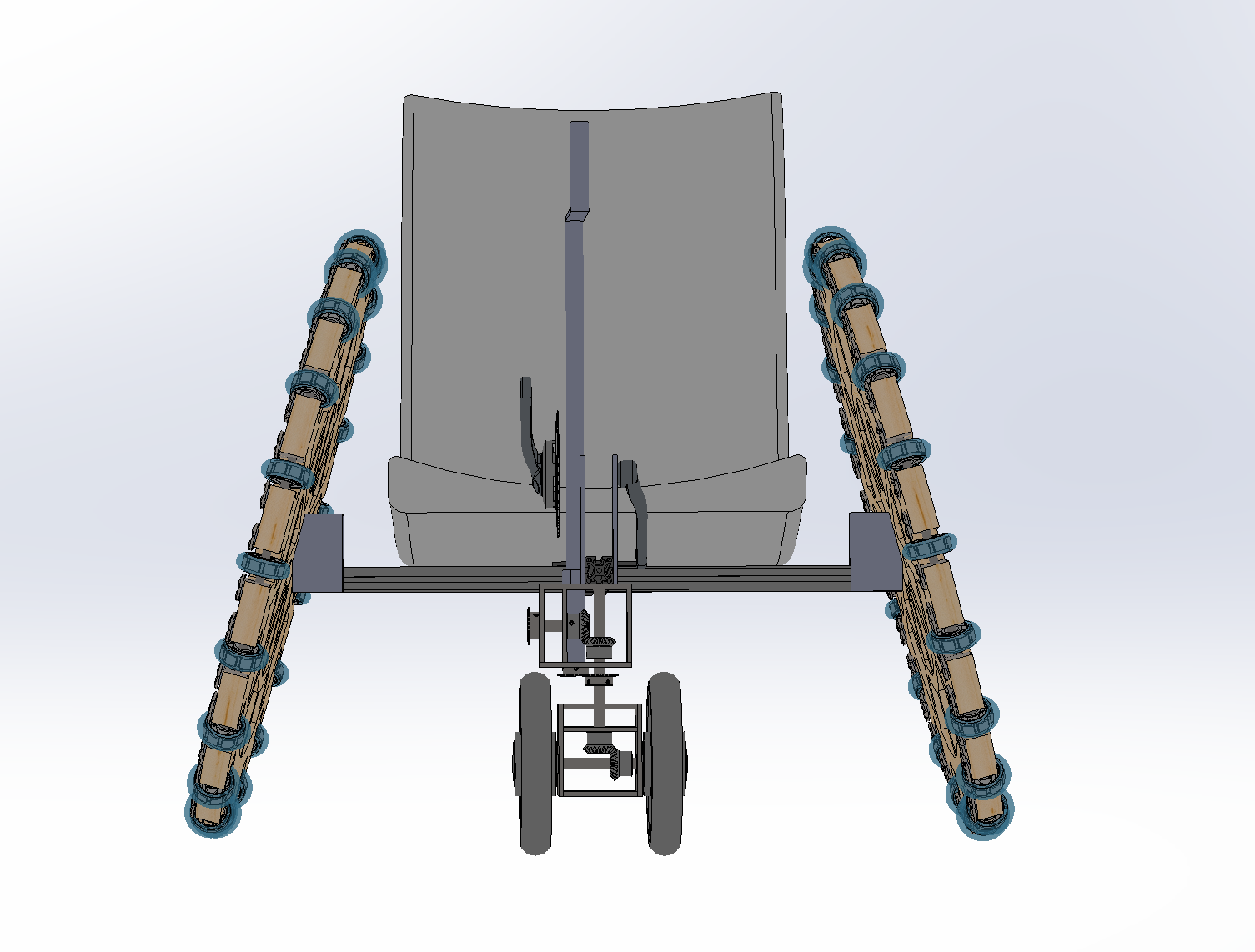
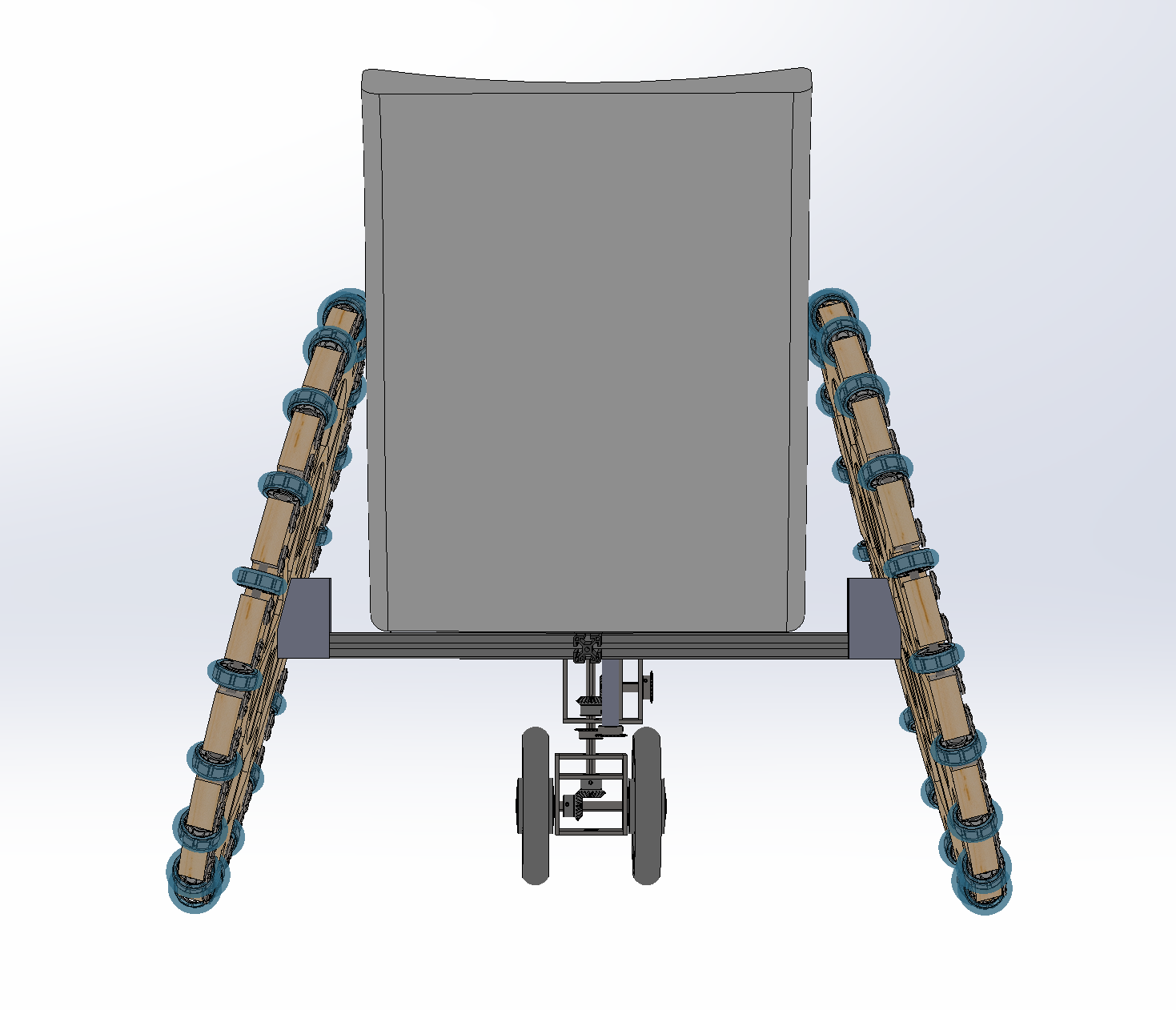
This vehicle idea took a different approach. We began to search for vehicles that already completed most of the tasks required. This led us to thinking towards a wheelchair design, which is capable of moving forward, backwards, and zero radius turns. The only issue was moving horizontally. By manipulating the large wheelchair wheels and adding perpendicular skate wheels and a steered powered wheel horizontal movement can be completed. The benefits of this design is that when moving horizontally, the drive wheel will be at the center and zero moments will be created about a pivot point and horizontal movement will be easily executed. The issue with the three wheels inline, was that in rough terrain maintaining all three wheel in contact with the floor would prove to be very difficult. The angle of attack of the large omni-wheels where introduced to mimimic wheel chairs used for racing. Caster wheels were placed purely for stabilization.

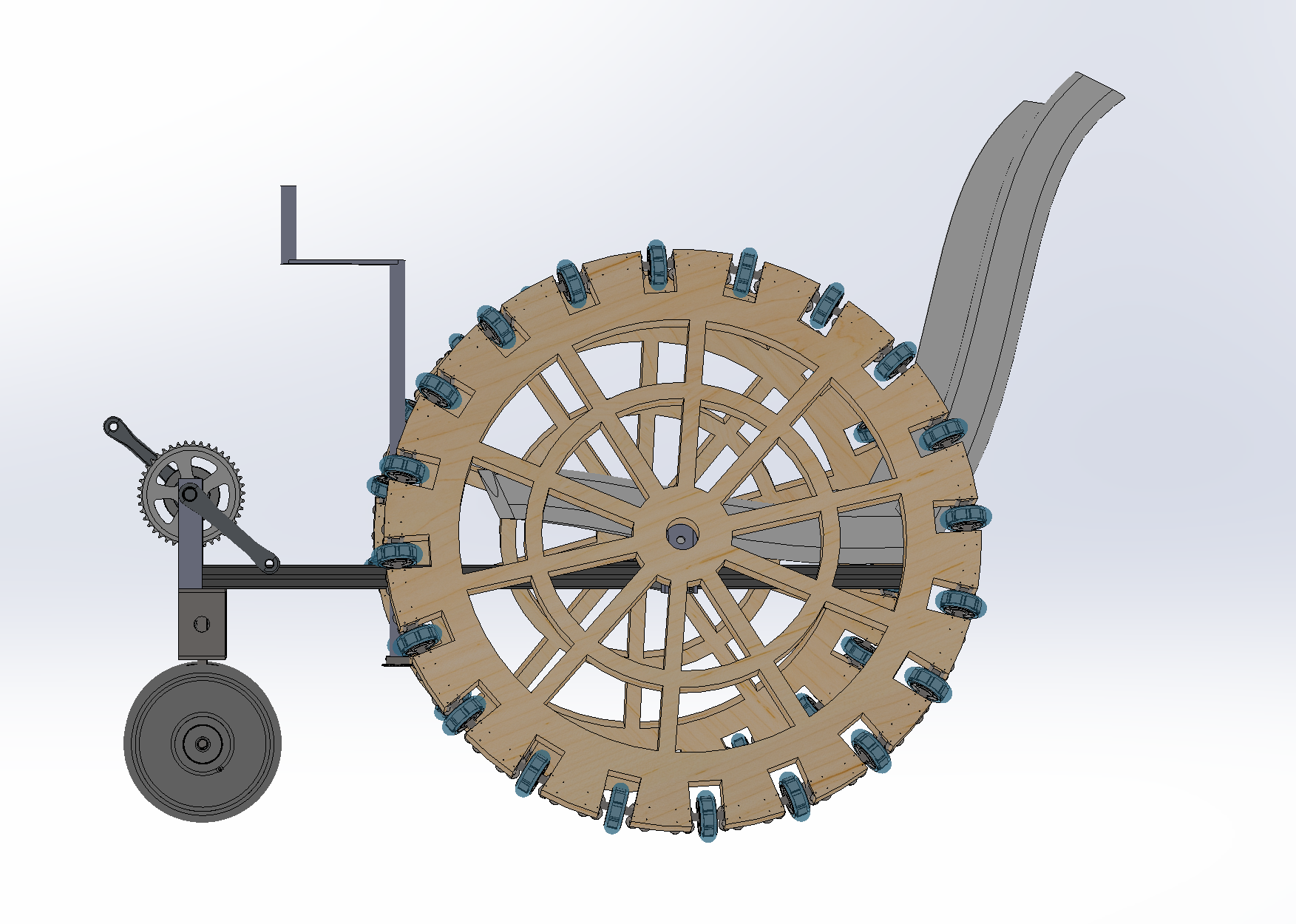


Vehicle idea 3
This vehicle is similar to vehicle idea 2, except the steered powered wheel was located in the front, making the vehicle a front wheel drive. The front wheel would be controlled with a shaft located in between the legs. The shaft had to be high enough to clear the drivers knees when pedaling. In order for this vehicle to move horizontally the steered driven wheel needed to be fixed at a 90 degree angle, parallel to the skate wheels, while one of the large omni-wheels is maintained fixed. This is because the powered steered wheel is not located under the center of mass and therefore would create a pivot, perfect for zero radius turning. Keeping one hand on the drive shaft and one hand on the omni-wheel will provide all translational movements as well as zero radius turning. This idea was not ergonomic and showed difficulty in controlling specific movements such as horizontal and 45 degree translations.


Vehicle idea 4
The issue with vehicle idea 3 was the ergonomics of the control system. Because one hand must remain on the control system of the drive wheel and one hand must remain on one of the large omni-wheels a new controls system was implemented to easily and comfortably be able to have both hands on both locations. This vehicle would have a powered driving wheel in the front that is controlled by a handle bar mechanism which has a gearing ratio of 3/1 with the drive wheel. Turning the handle bars 30 degrees will turn the drive wheel 90 degrees. Fixing the drive wheel at 90 degrees while pushing the large omni wheels in opposite directions will allow for zero radius turns. Fixing one of the omni-wheels and powered driven wheel will allow for all translational movements including horizontal, lateral, and diagonal. The seat of the vehicle would be designed to prevent movement at 30 degrees which will prevent movement of the driven wheel at 90 degrees. This range of motion would allow for all possible translations and rotations.
Design Overview
Vehicle idea 4 was pursued. As an omnidirectional vehicle, our prototype has the ability to translate in any direction on the ground while the user remains in the same orientation. This was achieved through a combination of powered wheels that can rotate to face any direction and a set of large omni-wheels inspired by wheelchair wheels, that feature 30 small skate wheels placed on each wheel to allow motion perpendicular to the larger wheel’s motion. These combined allow for forward, backward, side to side and diagonal motion. In order to provide human power and lateral translation, a gearbox was implemented to transfer pedal power to a driven wheel on the ground.




Chassis
The chassis was designed to support all sub-assemblies while maintaining rigidity and focusing on ease of integration. A simple design was pursued to minimize machined parts and reduce fabrication time. Initially we considered a T-Slotted frame, plywood and foam composite, and a 2x4 wood frame. Although the plywood and foam composite would have saved us about 5lbs in weight, the T-Slotted frame offered advantages in ease of adjustability of components and provided a durable, rigid, modular base necessary for the structure of our design. Considering the design challenge of a max weight of 100lbs, a minimalistic design was pursued. The main frame was comprised of two T-Slotted aluminum bars connected by two 3”x 6” tee surface brackets and fasteners, designed specifically for T-Slotted framing. Slot cut outs were made using a mill to insert the steering mechanism and give a method to tension the chain.
Controls
The controls were designed to be intuitive, low effort, simple to manufacture; while providing all the maneuverability required for omnidirectionality. The steering mechanism geared to have about 3:1 ratio from handles to powered wheel to be able to provide the full 180-degree range of motion of the powered wheel. The limiting factor for this design was the fact that the powered wheel required a sprocket with a minimum of 20 teeth to be fixed to the lower gear box. Initially a 60-tooth sprocket was considered to create the required 3:1 ratio but was determined to be too heavy to implement. An alternate 3 sprocket system was implemented, which weighed 2 lbs less than the single 60- tooth sprocket. The system included a 28-tooth sprocket bolted and fixed to the wood steering bar, which connects to a 9-tooth sprocket creating the 3:1 ratio. An additional 20-tooth sprocket fixed with the 9-tooth sprocket was implemented to create the 1:1 ratio with the 20-tooth sprocket fixed to the gear box. This provided a very sensitive steering mechanism with very little friction.
A stress simulation was performed on the handle bars. A 45 pound force was applied on each handle in opposite directions while maintaining the center shaft and sprocket holes fixed. The finite element and motion analysis showed a minimum factor of safety of approximately 1.2, indicating that the handle bars are rigid enough to support difficult and precise maneuvers. The FEA stress simulation show the maximum stress is well below the yield strength, and therefore indicates that are handles will perform under these conditions.
Chair
The chair was designed to be fully rigid when applied pedal power, easily assembled, ergonomic and provide a motion constraint on the steering. The chair required two design components which included, withstanding both the weight of the passenger and the force necessary to pedal, as well as limiting the amount of freedom of the controls steering mechanism. The chair was designed to sit above the steering bar and a slot was created to ensure the control bar had a range of motion of 60 degrees, 30 degrees on both side of the neutral position. Triangle cutouts were strategically made for light weighting purposes, while maintaining structural integrity. Three additional structure pieces were added for stability and prevention of buckling. The seat was designed to be cut using the Shopbot and fit together like a puzzle. The chair will be fixed to the T-Slotted frame through four bolts located on the sides.
A finite element and motion analysis was conducted on the chair to ensure the rider’s safety when generating speed. The seat was fixed at the location where the bolts connect to the T-Slotted frame as well as locations where the seat rests on the frame. A 200 pound load was applied to the backrest of the seat to account for the force applied when pedaling. Another 400 pound load was applied to the seat to account for the weight constraints of the rider. The max stress of the chair was well below the yield strength, confirming the structure of the seat safe for all riders. A factor of safety of 8.7 was determined further concluding the rigidity of the structure.
Gearbox
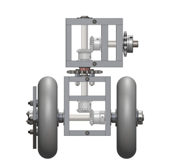
The gearbox was designed to enable steering to the front wheels (rotation of the lower gearbox), while also driving a wheel. This required the use of four bevel gears and two gearbox subassemblies (an upper gearbox and a lower gearbox). Pedaling transfers power from the horizontal shaft in the upper gearbox subassembly to the perpendicularly mounted bevel gears. The power is transferred to the vertical shaft and down into the bottom gearbox subassembly. The power is then transferred from the vertical shaft to the horizontal shaft in the lower gearbox subassembly through the perpendicularly mounted bevel gears and then finally to the driven wheel to rotate with the keyed shaft. The driven wheel rotated with the horizontal shaft by mounting a hub onto it that ensured that the wheel would rotate when the horizontal shaft rotated. The non-driven wheel was able to rotate freely and independent of the rotation of the horizontal shaft because it was able to rotate about the inner race of the bearings that were in contact with the shaft. Steering was accomplished by fixing the upper gearbox subassembly to the chassis and introducing a sprocket and chain drive to turn the lower gearbox.
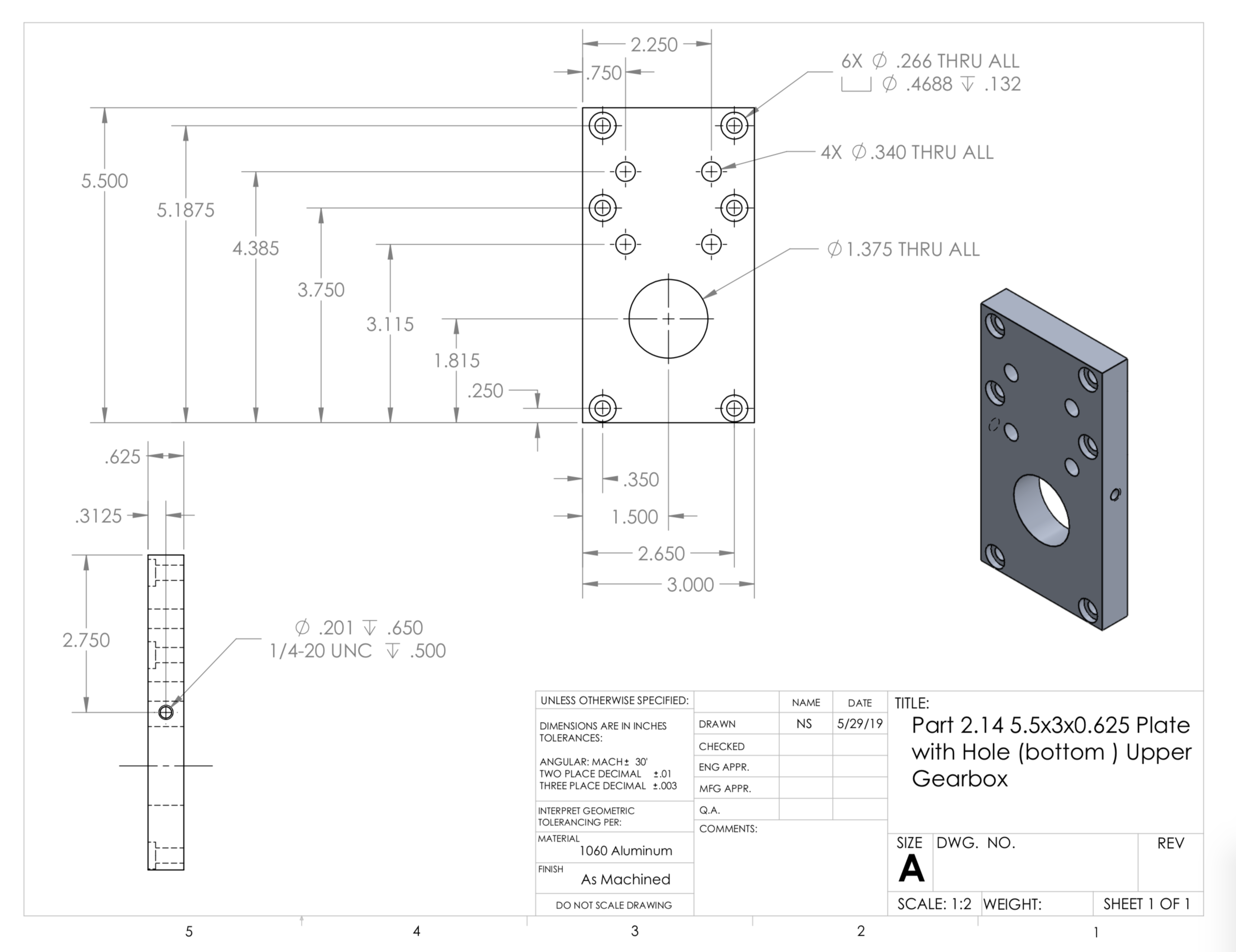
The plates for the gearbox involved intensive machining, and 2D and 3D programs on the ProtoTrak Mills were made to simplify the process. The locations of the holes on the plates of the gearbox had to be very precise because there were many clearance holes that had to line up properly with threaded holes located on other plates in order to assemble the gearbox. The pockets for the bearings also had to be created with care and precision because if they were out of place then the bevel gears wouldn’t mesh properly.


Large Omni-Wheel

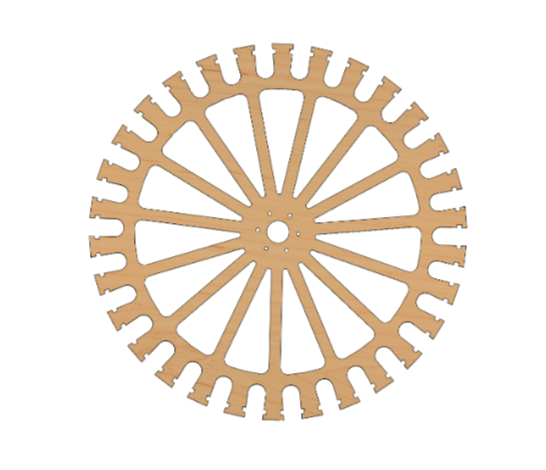

The wheels are constructed out of three layers of birch plywood, of varying thicknesses. The outer two layers are nominally 1⁄4 inch, while the center layer is 3.18 inches (8mm). The thickness of the center layer was determined by the diameter of the shaft through the skate wheels. To reduce the mass of the wheels, a spoke design was employed, in which 15 spokes supported the forces encountered by the wheel. All sharp corners on the design were filleted to mitigate stress concentrations. FEA stress analysis demonstrated that such a design would successfully bear the load of the vehicle plus the user. Each skate wheel has a 22mm bearing (8mm ID) press fitted onto a 40mm long, 8mm diameter shaft, which is then affixed into the center wheel. This shaft is held in place by the two outer layers, one of which is affixed to the center layer with wood glue, the other affixed with 1⁄4- 20 bolts. This allows us to remove one of the outer layers to make repairs or adjustments to the shafts and/or skate wheels.
A downward load was applied to the wheel, assuming the rest of the vehicle weights 70 lb and the user weighs 220 lb. It can be observed that the minimum factor of safety is 1.6, however, upon closer inspection, it becomes clear that the maximum stress concentrates around the 90 degree angles of the notches cut into the center layer of plywood. The simulation is likely calculating an overly high stress value, since a numerical calculation would inaccurately predict a very high stress concentration at the corner. Another point of high stress is on the fillet between the protruding sections of wheel, which represent a compressive stress. The actual wheel will have steel shafts spanning this distance, mitigating compressive stresses. Therefore we feel confident with the design based on this FEA given these caveats.
Omni-Wheel Frame Mount
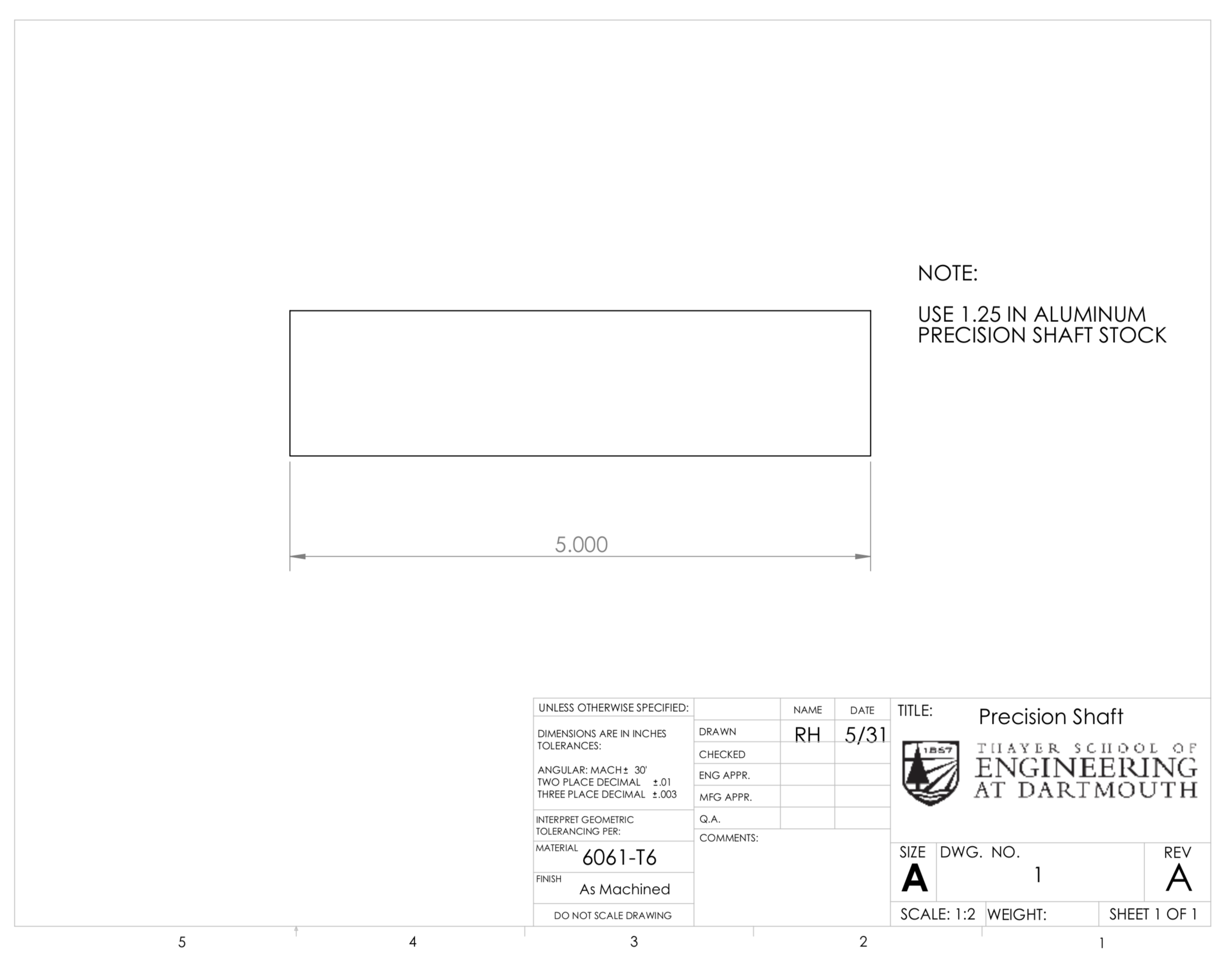
The Omniwheel Frame Mount was designed to interface the Omniwheels with the vehicle’s frame and provide a rigid, bearing mounted shaft on which the Omniwheels are mounted. The design intent of the frame mount aimed to minimize the need for machined parts in pursuit of a component that required little to no alteration prior to assembly. In addition, the design lent itself to easy assembly and installation due to the incorporation of T-Slotted framing and brackets. The shaft was selected based on an approximate stress analysis, achieved by modeling the shaft and its connections as a statically determinate beam. The beam was modeled with an applied point load of 200 lbs representing a total rider weight limit of 400 lbs. Additionally, to consider both static and dynamic loads, an applied moment of 4500 in∙lbs was introduced to simulate the wheel colliding with an object on the ground and acting as a lever arm. The maximum bending and shear stress were calculated to be used in the principle stress equation. The principle stress was calculated for shafts of varying diameters and material. Information about the density and length were provided to calculate the moment of inertia and mass of each rod. The aim was to compare the masses of various shafts available on McMaster and determine which rod was the lightest while still meeting stress requirements. Despite investigating hollow steels shafts, an aluminum shaft 1.25 inches in diameter was still the lightest option, providing a factor of safety of 2.5.
The SolidWorks simulation package was used to perform FEA on two critical components of the frame mount. The first component analyzed was the T-Slotted framing section. This analysis was performed to ensure that the T-Slotted framing component was sufficient in resisting the forces present during vehicle operation. A distributed load totaling 200 lbs was applied downward vertically and a distributed load of 50 lbs was applied to the inner faces of the pockets. The component was fixed on all sides to replicate its rigid connection to the frame. The FEA shows, the maximum stress in this component is well below the yield strength of the aluminum.
A FEA analysis was performed to ensure that the shafts in the frame mount would resist the forces present during vehicle operation. The shaft was fixed at each of the bearing locations and the bearings were fixed to simulate their seated position inside the T-Slotted framing. A total load of 200 pounds was applied to the underside of the shaft. The maximum stress is well below the yield stress of the aluminum shaft. In addition to this analysis, the displacement was verified to be less than a few thousandths of an inch.
Part Drawings


