10' Wingspan Flying Wing
Objective:
Build a 10’ wingspan flying wing that can be detached to fit in the back of a standard vehicle.
Skills Learned:
Dynamics of flight
3D modeling using unique shapes such as airfoil.
Machine shop skills such as laser cutting and hot wire foam cutting.
Role:
Mechanical Engineer with CAD SolidWorks modeling skills, in charge of creating 3D model for the team.
Research and design of airplane.
SOLIDWORKS Model


Plane Structure
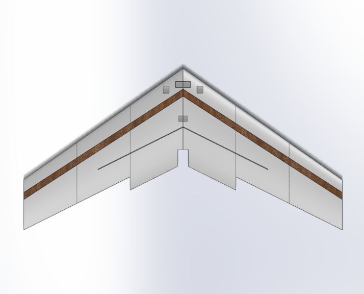
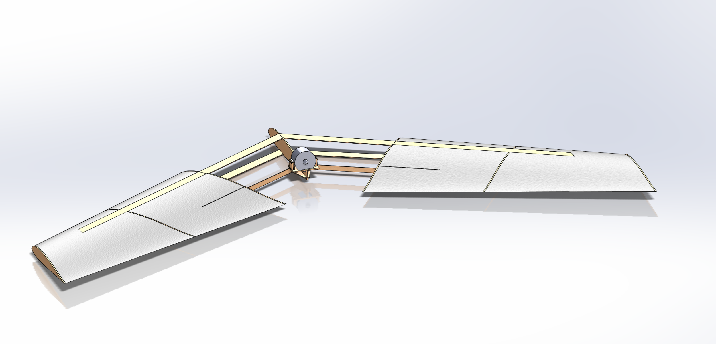
The planes internal structure consists of 5 ribs, an I-beam front spar with no web, and a vertical back spar.


Plane Cut Out Manufacturing Plan
The plane was initially going to be cut into 10 individual pieces using a hot wire technique. The reason for the separation of the cord length was to incorporate an I-beam through 2/3 of each wing. I-beam tests concluded that the web was no longer necessary therefore cutting the plane was reduced to 6 individual parts. Parallel cuts introduced complications with laser cutting pieces to fit together. Therefore perpendicular cuts with respect to the main spar were introduced for the ease of being able to laser cut all structure pieces and assemble.
Main Structural Spar


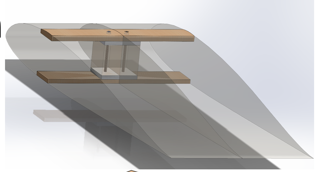
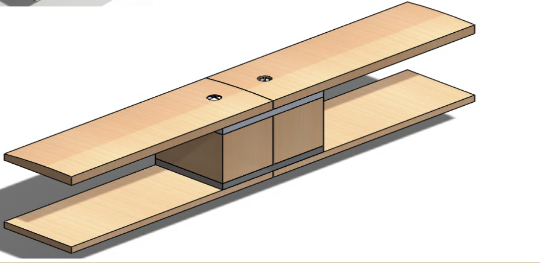
The main spar that provides the support for the flying wing is an I-beam that embedded into the foam cutouts of the plane. The further you go out on the wing the less structure is required, therefore the web of the I-beam is no longer required for the last third of the plane. Images of the I-beam structure are shown in the slide show to the left. The plane will have 3 main parts, the inner two sections, the left two sections, and the right two sections. Where these sections join together the spars will have a detachable mechanism included in the main spar. This mechanism is also shown in the slideshow to the left. Further I-Beam testing was conducted to determine the strength of the I-beam. Results concluded a web was not required and the structure was sufficiently strong enough for the 10’ wingspan flying wing. A model of the main spar without a web is shown below.
I-Beam Testing


Motor Mount
The motor mount will be connected to the main 1/4” plywood rib and intersecting 1/8” back spars. The main rib is connected to the 1/8” inch front spars that act as an I-beam structure through out the wings. The motor mount will be constructed out of 1/4” plywood and fitted together like a puzzle.


